Ac Circuits » Three phase power systems
Three Phase Power Systems
A single phase generator has one rotating coil with a cable going to the consumer units. A two phase generator has two coils on the same armature coiled at 90o to each other, with two cables going to the consumer units. In case of three phase systems, three coils are coiled at 120o to each other, with three cables going to the units. The different phase supplies are shown in the following figure. As far as AC generation on aircraft is concerned, three phase systems are generally used.
FIGURE
Characteristics of Three Phase Systems
- A combination of three single phase systems form a three phase system.
- Each power output is out of phase with the other voltages by 120o.
- The circuits require less weight of conductors than single phase circuits.
- Smaller size; less weight and more efficient when compared to single phase systems.
Split-phase power systems achieve their high conductor efficiency and low safety risk by splitting up the total voltage into lesser parts and powering multiple loads at those lesser voltages, while drawing currents at levels typical of a full-voltage system. This technique, by the way, works just as well for DC power systems as it does for single-phase AC systems. Such systems are usually referred to as three-wire systems rather than split-phase because "phase" is a concept restricted to AC.
But we know from our experience with vectors and complex numbers that AC voltages don't always add up as we think they would if they are out of phase with each other. This principle can be put to use to make power systems with even greater conductor efficiencies and lower shock hazard than with split-phase.
Suppose that we had two sources of AC voltage connected in series just like the split-phase system, except that each voltage source was 120° out of phase with the other.
FIGURE
Since each voltage source is 120 volts and each load resistor is connected directly in parallel with its respective source, the voltage across each load must be 120 volts as well. Given load currents of 83.33amps, each load must still be dissipating 10 kilowatts of power. However, voltage between the two "hot" wires is not 240 volts (120 z 0° -120 z 180°) because the phase difference between the two sources is not 180°. Instead, the voltage is:
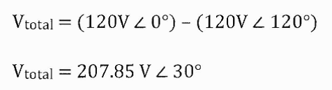
Nominally, we say that the voltage between "hot" conductors is 208 volts (rounding up), and thus the power system voltage is designated as 120/208.
If we calculate the current through the "neutral" conductor, we find that it is not zero, even with balanced load resistances. Kirchhoff's Current Law tells us that the currents entering and exiting the node between the two loads must be zero.
FIGURE
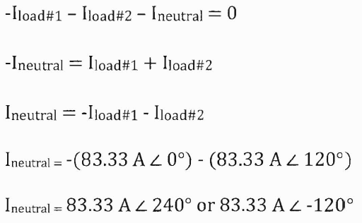
So, we find that the "neutral" wire is carrying a full 83.33 amps, just like each "hot" wire. Note that we are still conveying 20 kW of total power to the two loads, with each load's "hot" wire carrying 83.33 amps as before. With the same amount of current through each "hot" wire, we must use the same gauge copper conductors, so we haven't reduced system cost over the split-phase 120/240 system. However, we have realized a gain in safety, because the overall voltage between the two "hot" conductors is 32 volts lower than it was in the split-phase system (208 volts instead of 240 volts).
The fact that the neutral wire is carrying 83.33amps of current raises an interesting possibility: since it is carrying current anyway, why not use that third wire as another "hot" conductor, powering another load resistor with a third 120 volt source having a phase angle of 240°? That way, we could transmit more power (another 10kW) without having to add any more conductors. Let's see how this might look.
FIGURE
Let's survey the advantages of a three-phase power system over a single-phase system of equivalent load voltage and power capacity. A single-phase system with three loads connected directly in parallel would have a very high total current (83.33 times 3, or 250amps).
FIGURE
This would necessitate 3/0 gauge copper wire (very large!), at about 510 pounds per thousand feet, and with a considerable price tag attached. If the distance from source to load was 1000 feet, we would need over a half-ton of copper wire to do the job. On the other hand, we could build a split-phase system with two 15kW, 120 volt loads. (Figure below)
FIGURE
Our current is half of what it was with the simple parallel circuit, which is a great improvement. We could get away with using number 2 gauge copper wire at a total mass of about 600 pounds, figuring about 200 pounds per thousand feet with three runs of 1000 feet each between source and loads. However, we also have to consider the increased safety hazard of having 240 volts present in the system, even though each load only receives 120 volts. Overall, there is greater potential for dangerous electric shock to occur.
When we contrast these two examples against our three-phase system (Figure above), the advantages are quite clear. First, the conductor currents are quite a bit less (83.33amps versus 125 or 250amps), permitting the use of much thinner and lighter wire. We can use number 4 gauge wire at about 125 pounds per thousand feet, which will total 500 pounds (four runs of 1000 feet each) for our example circuit. This represents a significant cost savings over the split-phase system, with the additional benefit that the maximum voltage in the system is lower (208 versus 240).
One question remains to be answered: how in the world do we get three AC voltage sources whose phase angles are exactly 120° apart? Obviously we can't center-tap a transformer or alternator winding like we did in the split-phase system, since that can only give us voltage waveforms that are either in phase or 180° out of phase. Perhaps we could figure out some way to use capacitors and inductors to create phase shifts of 120°, but then those phase shifts would depend on the phase angles of our load impedances as well (substituting a capacitive or inductive load for a resistive load would change everything!).
The best way to get the phase shifts is to generate it at the source: construct the AC generator (alternator) providing the power in such a way that the rotating magnetic field passes by three sets of wire windings, each set spaced 120° apart around the circumference of the machine as in the following figures.
FIGURE
Together, the six "pole" windings of a three-phase alternator are connected to comprise three winding pairs, each pair producing AC voltage with a phase angle 120° shifted from either of the other two winding pairs. The interconnections between pairs of windings (as shown for the single-phase alternator: the jumper wire between windings 1a and 1b) have been omitted from the three-phase alternator drawing for simplicity.
In our example circuit, we showed the three voltage sources connected together in a "Y" configuration (sometimes called the "star" configuration), with one lead of each source tied to a common point (the node where we attached the "neutral" conductor). The common way to depict this connection scheme is to draw the windings in the shape of a "Y" like in the figure below.
FIGURE
The "Y" configuration is not the only option open to us, but it is probably the easiest to understand at first.
FIGURE
Our current is half of what it was with the simple parallel circuit, which is a great improvement. We could get away with using number 2 gauge copper wire at a total mass of about 600 pounds, figuring about 200 pounds per thousand feet with three runs of 1000 feet each between source and loads. However, we also have to consider the increased safety hazard of having 240 volts present in the system, even though each load only receives 120 volts. Overall, there is greater potential for dangerous electric shock to occur.
When we contrast these two examples against our three-phase system (Figure above), the advantages are quite clear. First, the conductor currents are quite a bit less (83.33amps versus 125 or 250amps), permitting the use of much thinner and lighter wire. We can use number 4 gauge wire at about 125 pounds per thousand feet, which will total 500 pounds (four runs of 1000 feet each) for our example circuit. This represents a significant cost savings over the split-phase system, with the additional benefit that the maximum voltage in the system is lower (208 versus 240).
One question remains to be answered: how do we get three AC voltage sources whose phase angles are exactly 120° apart? Obviously we can't center-tap a transformer or alternator winding like we did in the split-phase system, since that can only give us voltage waveforms that are either in phase or 180° out of phase. Perhaps we could figure out some way to use capacitors and inductors to create phase shifts of 120°, but then those phase shifts would depend on the phase angles of our load impedances as well (substituting a capacitive or inductive load for a resistive load would change everything!).
The best way to get the phase shifts we're looking for is to generate it at the source: construct the AC generator (alternator) providing the power in such a way that the rotating magnetic field passes by three sets of wire windings, each set spaced 120° apart around the circumference of the machine.