Aircraft Fasteners » Screw thread terminology
Screw Thread Terminology
It is often disputed as to the difference between a bolt and a screw. But, it is accepted that a bolt is considered to be a threaded fastener, which has a definite plain portion on the shank between its head and the beginning of the thread. This is used in conjunction with a nut, whereas a screw is threaded all the way to the head.
As there are so many variations in terminology with the numerous manufactures, the only safe way of describing a threaded (or any other) fastener is to use the correct terminology found in the relevant IPC, when ordering replacement items.
When defining the length of bolts, reference is usually made to the length of the plain portion of the shank of hexagonal-headed bolts (refer to figure below), while screw lengths are designated differently, according to their type.
FIGURE
Screw threads are usually formed with a ‘clockwise’ turning groove and are referred to as ‘right-hand’ threads. But there are occasions where the thread is formed with the groove spiralling in an ‘anti-clockwise’ direction and in this instance, they are designated as ‘left-hand’ threads.
While a traditional thread shape can be used to illustrate the terminologies associated with screw threads (refer to figure below), the actual profile of any thread will be determined by the Standard or specification to which it is manufactured. Of course, this will also be influenced by the use to which the threaded item is to be put.
FIGURE
The following terms are used to define the characteristics of a threaded item:
- Major Diameter: The largest diameter of the thread, measured at right angles to the axis.
- Minor Diameter: The smallest diameter of the thread, measured at right angles to the axis.
- Pitch: The distance from the centre of one crest to the centre of the next, measured parallel to the axis.
- Depth of Thread: The distance between the root and crest, measured at right angles to the axis.
- Lead: The distance a screw moves axially in one complete turn. In the case of multi-start threads, the lead is equal to the pitch multiplied by the number of starts.
- Single Start Thread: Term used when there is only one screw thread cut in the material.
- Multi-Start Thread: Consists of two or more separate, parallel threads cut into the material carrying the thread. This method is used in order to achieve a quick-acting motion between two threaded items.
- Runout: The part of the thread where the minor diameter increases until it equals the major diameter and merges with the plain portion of the shank. The runout cannot be used and any nut rotated onto the runout would become ‘thread-bound’.
Screw Thread Forms
The form of a screw thread will depend upon the function for which it is to be used (refer to figure below). Where the thread is used to join components together (nuts, bolts, screws and studs) then the conventional, truncated ‘V’-shaped threads similar to the ISO Metric thread will be found.
Turnbuckles and similar devices (which are employed as adjusters of either the tension or of the distance between components) may also use ‘V’-shaped threads, while the Acme, Buttress and Square threads are utilised to transmit movement or power (as may be seen in lathes, vices and Flap Jacks).
FIGURE
Thread forms have developed over the years, from the early standardisation on the BSW thread (with its rather coarse thread, which was prone to slackening when subjected to vibration) to the modern, finer threads which are more suitable for use on aerospace components and structures.
In an attempt to provide a common standard, Canada, the United States of America and the United Kingdom adopted the Unified system of threads.
Later, the International Standard Organisation (ISO) recommended that the Unified system be used internationally in parallel with a system using Metric units of measurement, but with a similar form of thread profile and standards of tolerances.
Unified Coarse (UNC) and Unified Fine (UNF) threads may be found wherever their use is appropriate. But special threads, such as UNS (for high-temperature applications) and UNJ (increased fatigue strength) have become more common.
Screw threads may be formed by such processes as tapping, dieing and machine cutting or (where maximum fatigue resistance is required of a bolt) by rolling.
Other Thread Forms
In the United States, a parallel but differing group of thread systems is used. The four main systems are ANC, ANF (also referred to as AF), UNC and UNF, with the NC and NF having a finer thread than the UNC and UNF.
Classes of Fit
In addition to being identified as either coarse or fine, the threads are also classified by their class of fit, as can be seen in table below.
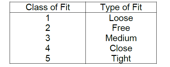
A Class 1 fit can be tightened all the way down by hand (such as with a wingnut), whilst a Class 4 or 5 fit requires a spanner throughout the tightening operation.
The Class 3 fit is the type mostly employed on aircraft and would be typical of a thread, which is designed for use in a high-temperature environment and may require the application of an anti-seize compound before installation.
By comparison, a fastener which is going to be subjected to the high tension or shear loads, associated with the securing of aircraft engine parts, would need to be a Close tolerance type of fit.
Measuring Screw Threads
It is not considered a normal operation to measure a screw thread, as its identification can be found in the IPC and supplied under a manufacturer’s part number. Whilst this is true and the manuals should always be used, there are other ways of identifying screw threads.
One method is to identify the screw by means of various marks, normally found on the head of the screw. These marks may give a clue as to which type of thread the screw has (AF, BSF or Metric etc.). A measurement across the thread crests using a micrometer would give the diameter of the screw in question. Finally, the identifying head markings would also give the material from which the screw is made.
Two useful tools (refer to figure below) may be used for different stages of thread measurement. The profile gauge can be used to ensure that the tool, which is cutting the thread, is of the correct type. The pitch gauge can be used to find the thread size by simply fitting the various blades of the gauge against the screw thread until a match is achieved.
FIGURE