Aircraft Fasteners » Bolts
Bolts
The bolts, used in the construction of aerospace components and structures, have evolved into a bewildering range of materials, shapes and sizes, all of which are dictated by the applications for which the items have been designed.
Standards and systems have been established, to provide identification of the many different forms of threaded devices, in order to ensure that only the correct items are installed in the relevant locations.
It is stressed here, that only the approved design materials may be used for aerospace components and while a selection of some of the bolts are presented in these course notes. By way of introduction, the relevant AMM, SRM and IPC will be the sole authority for deciding the correct type of bolt that is to be used in a particular application.
British Bolts
An extensive range of bolts and screws is provided for, in the specifications drawn up by the Society of British Aerospace Companies (SBAC). The following abbreviations (some of which have already been discussed are in common use:
- AGS: Aircraft General Standard
- AS: Aircraft Standards
- Al. Al.: Aluminium Alloy
- BA: British Association
- BSF: British Standard Fine
- HTS: High Tensile steel
- HTSS: High Tensile Stainless Steel
- LTS: Low Tensile Steel
- SS: Stainless Steel
- UNC: Unified National Coarse
- UNF: Unified National Fine.
Identification of BS Unified Bolts
British Standard Unified (BS Unified) bolts are identified by the use of an alphanumeric code, which provides information relating to the type, material, surface finish, length, diameter and any other important characteristics of the threaded device.
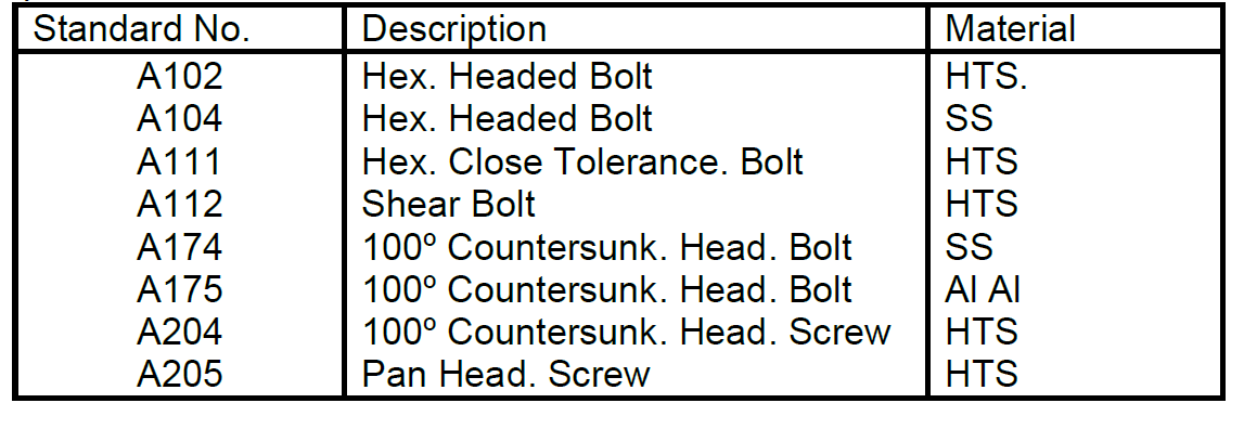
The following table shows a (very small) selection of aircraft standard bolts and screws with a (shortened) description of the type of device and the materials from which it is made.
Reference to the table shows that the code A102 signifies a hexagonal-headed bolt which is made of high-tensile steel, while the code A175 represents a 100° countersunk-headed bolt made from an aluminium alloy.
Other methods of indicating that an item has a Unified thread are:
- Three contiguous (touching) circles marked in a convenient position (machine items).
Note: Due to the difficulty in applying the identifying marks to individual items, it is planned to merely mark the packets in which the threaded devices are marketed, so that some/all of the identification marks will not be seen on the items (particularly screws). Therefore, great care must be taken to ensure that the items being used are correctly identified and to the approved standard.
- A shallow recess in the head of a bolt, equal to the nominal diameter of the thread (cold forged items).
- A ‘dog point’ (small protrusion) on the threaded shank end (usually applies to screws).
Further numbers and letters are added to the identifying code, to provide information relating to the length (usually of the plain shank or gripping portion) and to the diameter of the items. The length is given by a number, which signifies increments of tenths of an inch, so that a 5 would represent a bolt with a plain shank of 0.5 in, while the number 12 would signify the plain shank as being 1.2 in long.
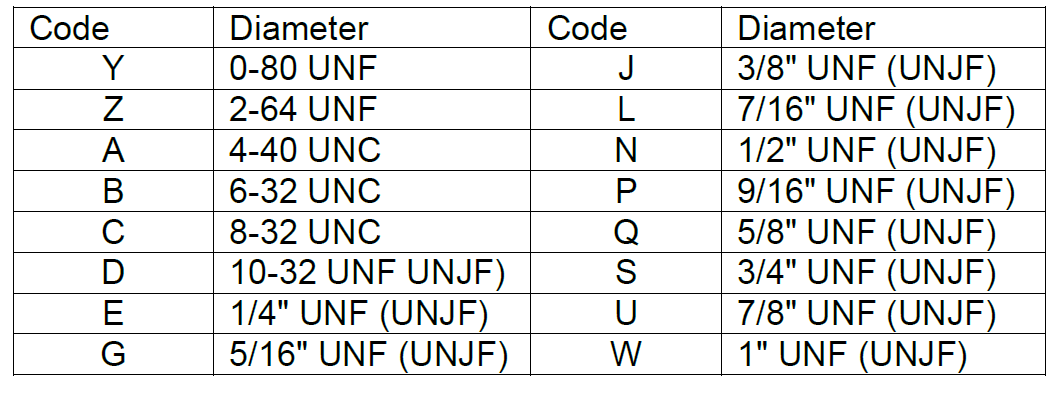
Reference to table below, will show how the diameter of an item is designated by the addition of another letter to the system, so that a bolt with the code marking of A102 9 E, would signify a Unified-threaded, hexagon-headed bolt, made from high-tensile steel with a plain shank length of 0.9 in, and a diameter of ¼ in.
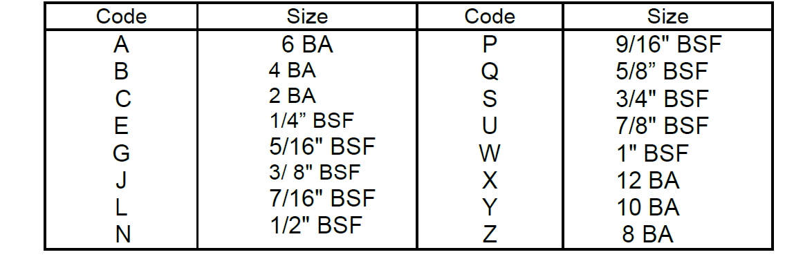
Note: In the earlier UK system (which may be encountered on older or home-constructed, light aircraft), bolts more than ¼ inch diameter are normally BSF, whilst bolts less than ¼ inch diameter (and most screws) are BA. Both of these items also use a number to represent their nominal length and a letter code (as can be seen in table below) to identify their diameter.
Other bolts of this era may have nicks at the corners of the head (High Tensile Steel) or a raised ring on the bolt head (Cold Rolled) to assist differentiation of their particular designations.
American Bolts
American aircraft bolts and nuts are threaded in the NC (American National Coarse), the NF (American National Fine), the UNC (Unified National Coarse) and the UNF (Unified National Fine) thread series. The item is often coded to give the diameter of the threaded portion and the number of threads per inch (tpi).
Aircraft bolts may be made from HTS, Corrosion-Resistant Steel or Aluminium Alloy. Head types may be hexagonal, clevis, eyebolt, internal wrenching and countersunk (refer to figure below) and head markings may be used to indicate other features such as close tolerance, aluminium alloy, CRS or other types of steel.
FIGURE
Identification of an Standard Bolts
While there are several different US Standards, there is only need to discuss one type for the purpose of these course notes, as the others are very similar.
AN bolts come in three head styles, Hexagon Head, Clevis and Eyebolts and the following table provides an indication of the various code numbers in use.
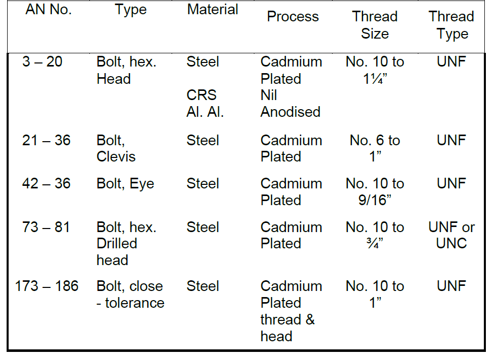
Note: The later series uses a different number system.
For identification purposes, the AN number is used to indicate the type of bolt and its diameter. In addition, a code is used to indicate the material, length and presence of a split pin or locking wire hole as follows:
- Diameter: The last figure or last two figures of the AN number indicates thread diameter, 1 = No.6, 2 = No.8, 3 = No.10 and 4 = ¼” with subsequent numbers indicating the diameter in 1/16” increments. Thus an AN4 is a hexagon headed bolt of ¼” diameter and an AN14 is a hexagon headed bolt of 7/8” (14/16”) diameter.
- Lengths: The length of a bolt in the case of a hexagonal headed bolt, is measured from under the head of the first full thread (refer to figure below) and is quoted in 1/8” increments as a dash number. The last figure of the dash number represents eighths and the first figure inches, so that an AN4 – 12 is a ¼” diameter hexagon headed bolt, 1¼” long.
FIGURE
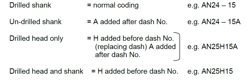
- Position of Drilled Hole: Bolts are normally supplied with a hole drilled in the threaded part of the shank, but different arrangements may be obtained.
- Material: The standard coding applies to a non-corrosion-resistant, cadmium-plated steel bolt. Where the bolt is supplied in other materials, letters are placed after the AN number as: C = Corrosion Resistance Steel C.R.S. e.g. AN25C15; DD = Aluminium Alloy e.g. AN25DD15.
- Thread: Where the bolt is supplied as either UNF or UNC threads, a UNC thread is indicated by placing an A in place of the dash. e.g. AN24A15.
Special-To-Type Bolts
The hexagon headed aircraft bolt AN3 – AN20 (refer to figure below) is an all-purpose structural bolt used for applications involving tension or shear loads where a light drive fit is permissible.
FIGURE
Alloy steel bolts smaller than 3/16” diameter and aluminium alloy bolts smaller than ¼” are not used on primary structure. Other bolts may be used as follows:
- Close Tolerance Bolts: These bolts are machined more accurately than the standard bolt. They may be hexagon headed (AN173 – AN186) or have a 100º countersunk head (NAS80 – NAS86). They are used in applications where a tight drive fit is required (the bolt requires the use of a 340-400g (12-14oz) hammer to drive it into position.
- Internal Wrenching Bolts: These bolts (MS20024 or NAS495) are fabricated from high-strength steel and are suitable for tensile or shear applications. The head is recessed to allow the insertion of a hexagonal key used for installing or removing the bolt. In dural-type material, a heat-treated washer must be used to provide an adequate bearing surface for the head.
- Clevis Bolts: The head of a clevis bolt is round and either slotted for a standard screwdriver or recessed for a cross-pointed screwdriver. This type of bolt is used only for shear loads and never in tension. It is often inserted as a mechanical pin in a control system.
- Eye Bolts: The eye is designed for the attachment of cable shackles or turnbuckles and the bolt is used for tensile loads. The threaded end may be drilled for ‘safetying’.
Metric Bolts
The identification of a Metric bolt is by the use of the diameter in millimetres, immediately after the capital letter ‘M’. In this way, M6 represents a 6mm diameter bolt. The length is also shown in millimetres, so the bolt M6-15 will be a 6 mm diameter bolt, which is 15 mm long. The basic terminology for identifying bolts of the Metric system involves the nominal length, the grip length and diameter (refer to figure below).
FIGURE