Semiconductors » Diode » Testing diodes
Testing diodes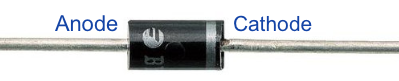
1. Testing diodes using Digital Multimeter
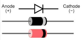
Step 1: Identifying a diode
A Diode has two terminals Anode (+) and Cathode (-). The shaded portion at the end of the diode can identify the terminals. Terminal near the shaded portion is Cathode (-) and other one is anode (+).
Step 2: Diode testing instrument
A diode can be tested using Digital or Analog Multimeter. Turn the knob to towards the “diode test” range that is marked with a diode symbol in the multimeter.
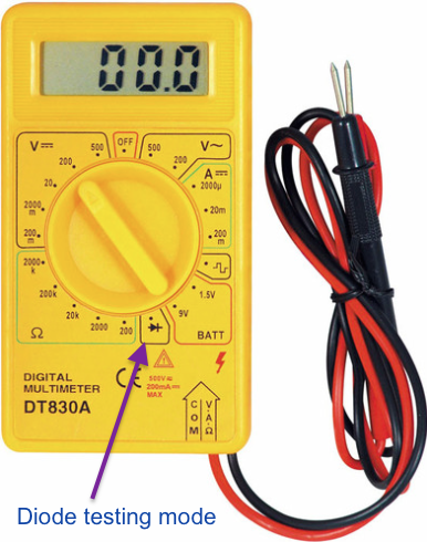
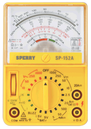
Digital and Analog Multimeters
Step 3: Testing the diode
Testing silicon diodes
For forward biased
Connect black lead (Negative lead) to the cathode and red (Positive lead) to the anode. Multimeter will show the forward voltage drop between the two testing leads. Reading may vary from diode to diode and meter to meter. However a healthy silicon diode should read around 0.6 Ω to 0.7Ω in forward bias.
For reverse biased
Connect black lead (Negative lead) to the anode and red (Positive lead) to the cathode. If the multimeter shows an infinite reading, then the diode is considered healthy.
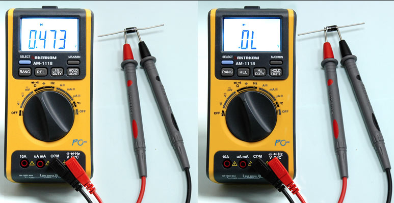
Image source: Electronic robotic
Testing Germanium diodes
When testing Germanium diodes follow the same procedure. Now the reading should be between 0.25 to 0.3 V for forward biased and infinitive for reverse biased to indicate healthy condition.
2. Testing diodes using analog multimeter
Testing ordinary silicon diode
For forward biased
Place the selector switch at the low resistance position (around 1K). Connect the positive lead to anode and the negative lead to cathode. If meter shows a low resistance reading, diode is healthy for forward biased mode.
For reverse biased
Place the selector switch at the high resistance position (around 100k) Connect the positive lead to cathode and the negative lead to anode. If the meter reads infinitive or very high resistance, diode is healthy for reverse biased mode.
For detail reading follow this link circuits today